International Patents applied for by Robert D. Hunt
ABSTRACT
A sea glider having long narrow, high aspect ratio wings in order to produce a high glide ratio and having a hydro-turbine coupled to the sea glider to generate power via the movement of the submersible through water to harness kinetic energy from the forward motion of sea gliding. The sea glider is innovatively coupled to a surface sled that remains on the surface of the water to produce energy from wind via a wind turbine and solar energy via solar cells as the sea glider moves underwater. The sea glider and surface sled are connected via a tube that contains a bundle of individual lines for; radar, GPS, and visual communications, to supply compressed air from the surface sled to the submersible for ballast control and for breathing by occupants, to allow spent air to return to the surface to a lower pressure, to provide warning notification at the surface of the presence of the sea glider underwater. The shaft of the wind turbine on the surface sled is coupled to an air compressor to produce compressed air that is held within the pressure vessel pontoons of the surface sled.
BACKGROUND
It is well known that air and water are both lifting
fluids. Air is merely a more dilute lifting fluid than is water and the
principals of science that work in water also work the same in air or;
conversely, the scientific principals that work in air work the same in
water.
Scientists could not understand how marine mammals traveled for great
distances when their food intake which represents their energy input was
so low that it would be impossible for them to swim such great distances,
when their movements are calculated as a thermodynamic power cycle relating
to energy input and energy output -- as their output of energy appeared
to be far greater than their input of energy. They have since learned
that the marine mammals use gravity to glide upward and downward through
the water.
The mammals after taking in air from the atmosphere at the surface of the water, compress the air to a higher density and a smaller volume within their bodies using their muscles with a simple quick movement that causes them to physically become smaller and heavier than the surrounding water so that they glide downward and forward from the surface. When the mammal desires to rise they can release the force applied by their muscles, causing their physical size to become larger and causing the air within their bodies to expand to a lower density and to a greater volume, which in turn causes the mammal to become lighter-than-water.
The force of buoyancy, the greater pull of the earth’s
gravitation field on the water than on the low density air within the
mammal, causes the mammal to rise upward and forward. The forward motion
is caused by the resistance of the water to the upward motion, which deflects
a portion of the upward motion into a forward motion, known as sea gliding
that works exactly the same as an aerodynamic glider works in air. The
energy input of these mammals to provide propulsion through the water
is quite minimal -- merely quick muscular movements periodically in order
to glide upward and downward through the water as they change from being
heavier-than-water to being lighter-than-water. Thus the mystery of how
long range migration of marine mammals is accomplished was solved by discovering
their use of gravity’s two forces – buoyancy and gravity acceleration
-- in an alternating cycle.
Conventional sea gliders, like their mammal cousins, glide both upward
and downward through the water via alternating between buoyancy and gravity
acceleration and use almost no battery power to operate as they travel
enormous distances. The energy input in order to sea glide is so minute
that one small battery can operate a sea glider for over a year of continuous
travel. From a thermodynamic efficiency calculation the sea gliders get
far more momentum energy out of the process than is put in as an energy
source to provide periodic ballast changes. They harness gravity to provide
propulsion.
Sea gliders use a power source, such as an electrical
battery, to provide guidance and control of the craft. The amount of power
available for the craft is usually extremely minimal and the duration
of operation is determined by the amount of stored power that is provided
by this power source; however, even with this small power source, sea
gliders potentially can operate for more than a year.
Sea gliders harness gravity via mass differentials and this can be proven
by their existing operation as opposed to complex mathematical computations.
A state-of-the-art conventional thruster powered underwater vehicle can
operate for approximately four hours at a velocity of approximately five
knots with the best batteries available today that are much larger than
those typically used by sea gliders. By comparison a sea glider can operate
for up to a year of continuous motion at a velocity of near .5 knot. If
the sea glider used its battery power to propel the craft at the same
.5 knot velocity like a powered underwater vehicle in level horizontal
motion instead of obtaining gravity power by sea gliding, it would only
operate for hours or days at best before using up all of its available
power. The energy to accomplish the additional range and extended duration
of operation is provided by harnessing gravity via mass differentials
– alternating from being heavier-than-water to being lighter-than-water
in a continuous cycle.
Current sea gliders rise by pumping an oil contained inside the hull into
external sacks to increase the volume of the sea glider or use a piston
called a “buoyancy pump” located in the nose of the sea glider
to discharge water from the hull or inflate a balloon type of gas bag
within a flooded section of the tail of the sea glider. Further, it is
proposed that sea gliders use a temperature differential to alter the
craft from being heavier-than-water to being lighter-than-water, using
the ambient temperature of the water, which varies by depth. However,
great depth must be accomplished in order to provide sufficient temperature
differential for this process to work. And, this is a slow process that
provides minimal change in the mass differential of the craft in relationship
to the mass of the water, which in turn provides a very slow velocity
to the sea glider, as the rate of upward and forward movement via buoyancy
or the rate of downward and forward movement via gravity acceleration
is a function of the degree of mass differential in mass density between
the mass density of the sea glider and the mass density of the water.
Air gliders use very long high aspect ratio wings that are designed with a high degree of aerodynamic capacity in order to obtain very high glide ratios with the most advanced air gliders now obtaining a glide ratio of 100 to 1. The glide ratio extends the duration of flight and the range of the flight, while not affecting the glide speed which is a function of the degree of mass differential alone. An air glider increases its velocity with an increase in weight (increase in the degree of mass differential) with no loss of glide ratio.
Prior art sea gliders unlike their airborne counter-parts
do not use high aspect ratio wings to provide greater sea gliding ratios
that would further extend their duration of glide and range. In large
measure current sea gliders are merely torpedoes with extremely short
poorly hydro-dynamically designed wings that provide poor glide ratios.
Further, it is proposed that sea gliders surface and to recharge their
batteries using solar energy. However, this strategy has serious drawbacks,
because the sun only shines for a portion of the time, it takes substantial
time to produce and store solar power via photovoltaic solar cells, and
the submersible is subject to detrimental tidal movements and wind forces
while remaining on the surface in order to charge its batteries via solar
power, etc.
Small sized sea gliders have historically been used for scientific purposes, such as measuring tidal movements, salinity and temperature changes, etc. and have not been used as a mode of transportation or as a mode of cargo transport. They are most often designed for extreme depth and are not designed for shallower depth sea gliding travel to avoid the high hydro-static pressure associated with greater depth.
Hydro-turbines produce power from the flow of water over the turbines’ blades. However, it is well known that power may be produced by the movement of a hydro-turbine through the water instead of the water moving over the hydro-turbine.
Wind powered boats have been constructed that use wind turbines for motive power instead of sails. Power from the wind turbine is transferred to a propulsion device in the water to propel the craft. Unlike sail boats, these craft are able to sail directly into the wind and produce their greatest power and velocity sailing directly into the wind. Existing wind powered boats using conventional horizontal axis wind turbines have achieved velocities exceeding thirty knots.
In pumped storage hydro-electric power plants, a pump powered by an electrical motor pressurizes water to a high elevation. In the reverse mode, pressurized water flows through the pump to cause it to become a hydro-turbine that powers a generator, which is the electrical motor, used in the reverse mode. This process is ninety percent efficient.
A stretched diaphragm has been designed to provide thousands of horsepower for short periods of time to launch torpedoes on submarines. Water is pressurized into one side of the diaphragm that is used as a biasing member, causing it to stretch in the opposite direction. The biasing member applies an equal and opposite force against the water as it stretches. Once the desired pressure has accumulated against the diaphragm, the vessel is sealed. Thus, the energy to launch the torpedo is stored and held for later use. When it is desired to launch the torpedo, a valve opens, which allows the water pressure to be applied against the torpedo within a cylinder launch tube and the water pressure launches the torpedo with great force. The stretched diaphragm is a method of energy storage.
Another problem with submersibles is occasional catastrophic loss due to insufficient buoyancy. Ships and submersibles occasionally are sunk into the depths of the sea. This happens in part because of the physics of increasing hydrostatic pressure. As a vessel sinks, the air or other gases retained within cavities becomes more and more compressed as the hydro-static pressure increases with depth, which in turn causes the gases to occupy a smaller and smaller volume as they compress. Smaller volume also means less lift capability via the principal of buoyancy, which may be stated as the principal of displacement. As the physical volume decreases due to compression, the area displaced also decreases. Also, pressure vessels containing gases, including the cabins of submersibles, often rupture releasing their gases due to extreme hydro-static pressure applied against the pressure vessels, causing loss of the lift the gases provide.
Once a vessel has lost lift at the surface and begins to sink in water, it is difficult to halt this process; and, as the process of increasing hydro-static pressure progresses, less and less buoyancy is available and the vessel disappears into the depths of the sea, usually ending up on the ocean’s floor and in the case of submersibles often with no survivors.
SUMMARY OF THE INVENTION
The invention herein disclosed is directed more specifically at solving many of the problems of current sea gliders by the innovative use of a hydro-turbine to generate power via the movement of the submersible through water that can generate and store power from the kinetic energy of motion as previously disclosed and the innovative use of a surface sled that can generate power from the motion of a wind turbine through the air and can generate power via solar power from the surface. Additional environmental energy resources that are available to a sea glider, including pressure differentials, temperature differentials, and current differentials, are also disclosed in detail herein. Further, the surface sled may prevent catastrophic loss of an attached submersible if the surface sled has sufficient lift capacity to hold the sea glider in a position so that it does not sink any further.
While the sea glider of the present invention may be constructed as a small research sized unit that is manned or unmanned, it is the intent of this patent application to disclose a sea glider capable of being constructed at a very large size that is capable of carrying cargo and passengers exceeding the capacity of a conventional surface ship. This may be accomplished because of the additional lift capacity of having the entire vessel submerged while a conventional ship only provides lift using the portion of its hull that is submerged for displacement. The apparatus of the present invention also gains the tremendous energy saving benefit of gravity powered sea gliding that is not available to a conventional surface ship.
The hydro-turbine generates power from the motion of the glider through the water to generate the needed power for operational and ballast control purposes and to produce additional power for other uses. A hydro-turbine will perform in an identical manner either when the hydro-turbine is stationery as water moves over its blades or when the turbine is attached to the sea glider as it moves through stationery water and, likewise, the wind turbine on the surface sled will operate by the motion of the sled through the air. Further, a hydro-turbine and water pump may be used as a thruster to provide propulsion when used in the reverse mode in which pressurized water drives the pump to power the thruster, which is the hydro-turbine used in the reverse mode. Two different processes to provide pressurized water to drive the pump in reverse mode and to provide energy from pressure differentials are disclosed herein: (1) the first being the use of an expanded diaphragm; and, (2) the second is the use of compressed air.
It has been proposed that sea gliders use the temperature differential found within the sea as a power source. This potentially is a slow and marginally effective process. In the present invention, energy may be produced by a hydro-turbine that may be used to heat a high vapor pressure low-boiling-point-liquid to provide a faster and more effective use of a phase change from the liquid to the gaseous phase to provide buoyancy in order to produce lift for a sea glider or conversely the gas may be cooled to reduce lift. The low-boiling-point-liquid may be heated by RF (Radio Frequency) microwaves, may be heated by electrical resistance heating coils, may be heated by thermoelectric modules, or other forms of heat generation derived from stored energy or from energy currently being produced by the hydro-turbine to change to the high pressure gaseous phase.
Further, it has been proposed that sea gliders surface and re-charge their batteries with solar energy. However, the innovative use of a surface sled provides additional methods by which energy may be generated from environmental energy sources. The surface sled allows a wind turbine to generate power from the force of the wind and it also allows solar energy to be gained from the surface via the connecting lines from the surface sled to the submersible.
In the preferred embodiment of the present invention, the sea glider does not have to be sea gliding in order to generate power. The sea glider may be held stationery by an anchor / counterweight that may be lowered to the bottom of the sea. A stationery sea glider may harness environmental energy from: (1) the tidal movement of water over the blades of a hydro-tubine; and, (2) wind energy via the wind turbine at the surface; and, (3) solar energy via solar cells from the sun at the surface; and, (4) the current differential between the wind and water.
Further, the sea glider does not even have to be anchored to generate power. Power can be generated by the opposing forces of the wind current energy and water current energy. Generally, the tidal current of the water will pull the sea glider underwater in one direction and the wind energy at the surface will pull the sled in a different direction, even if they are merely drifting in these currents, power is produced by the process. Power is obtained via the pressure differential created between current energy applied against the sea glider underwater and wind energy applied against the surface sled in the air that may be harnessed by the wind turbine and/or hydro-turbine respectively.
The innovation of a unique wind turbine that combines both solar energy production and wind energy generation is herein disclosed. Solar cells may be mounted onto the upper surfaces of the blades and support horizontal disk of the wind turbine as well as other structures on the surface sled to produce both solar and wind energy simultaneously.
The surface sled moves along the water’s surface and because it is open to the air it can provide: (1) real-time continuous communication capabilities for the submerged sea glider via a communication line, such as a fiber optic cable, connected to the submersible below water; and, (2) a supply of air to breath while submerged underwater via an air supply line connected to the submersible below water; and, (3) surface visibility via a fiber optic communication line connected to the submersible below water; and (4) radar surface detection and other electronic surface monitoring of the surface via a radar system mounted on the sled using a communication line, such as a fiber optic cable, connected to the submersible below water; and, (5) a stored air supply from the surface to use for ballast control on the submersible via an air supply line connected to the submersible below water that will allow the submersible to use air to blow ballast water out of the glider in order to gain buoyancy without having to rise to the surface to acquire air. The sled can hold a pressure vessel having a pressurized air supply without negatively affecting the buoyancy of the submersible because the pressure vessel filled with compressed air is not on the submersible itself but rather is on the surface on the sled. The tank can remain filled by a wind turbine driven air compressor that uses the kinetic energy of the motion of the wind turbine through the air and via the kinetic energy of the wind blowing along the water’s surface as an additional energy source; and, (6) notification of the presence of the submersible below water via the visible surface sled, like a diver’s flag floating on the surface, and via air bubbles that will continuously rise from the submersible, like a divers bubble trail. Emergency signals may be placed on the sled in order to provide notification at the surface that there is a problem with the submersible below and the submersible can be reeled to the surface via the connecting lines if necessary; and (7) ability to acquire GPS global satellite positioning while submerged all of the time to more accurately navigate the sea glider; and, (8) supply electrical power when the sun is shining that is produced via solar cells mounted on the sled and mounted on the horizontal disc and shutters of the wind turbine; and, (9) emergency location of the sea glider via the surface sled located at the surface with the sea glider attached below; and, (10) provides a means via return air lines from the sea glider to the surface sled to discharge spent air back to the lower pressure atmosphere, which requires less pressure than discharging air into the water which must be at a higher pressure than the hydrostatic pressure of the water in order to enter the water; and, (11) added safety from catastrophic loss of the sea glider as the surface sled will provide buoyancy for the sea glider to prevent it from going to the bottom of a deep ocean in the case of ballast system failure of the sea glider that makes it impossible for the sea glider to return to the surface on its own and will supply needed air to the sea glider until a rescue can be accomplished by pulling the sea glider up from the depths by its line connected to the surface sled.
Environmental energy and gravity power energy sources available to the sea glider are: (1) wind power from both wind energy from the environment; and, (2) wind energy from the motion of the wind turbine through the wind as the sled is pulled forward by the submersible; and, (3) hydro-power from the kinetic energy of motion of the submersible the surface sled through the water if it has a hydro-tubine attached that is under the surface of the water; and (4) hydro-power from the kinetic energy of motion of the submersible through the water with hydro-turbines attached to the sea glider; and, (5) hydro-power produced by the motion of water over the hydro-tubines while the sea glider and surface sled are stationery; and (6) power produced as a result of temperature differentials that occur due to changing depths within the water or as a result of height within the air in regards to an airship; and, (7) solar energy from solar cells mounted on the surface sled and wind turbine that remain at the surface all the time; and, (8) power generated from pressure differentials; and, (9) power generated from current differentials, using air currents at the surface acting upon the surface sled and water currents underwater acting upon the sea glider.
The sea glider of the present invention uses very long high aspect ratio wings that are designed with a high degree of aerodynamic capacity in order to obtain very high glide ratios of perhaps as high as 100 to 1. The glide ratio extends the duration of flight and the range of the flight, while not affecting the glide speed which is a function of the degree of mass differential alone. The glide ratio of the sea glider is very important because as the glide ratio increases more power is generated between ballast changes and a greater distance is traveled between ballast changes, which conserves valuable energy resources.
An improved glide ratio also means that a shallower glide
path may be followed. This is important if the purpose of the vessel is
to transport passengers and cargo and it is desirable for the craft to
be designed for shallower depth travel to avoid the high hydro-static
pressure associated with greater depth.
The sea glider of the present invention will increase its velocity with
an increase in the degree of mass differential with no loss of glide ratio
and will attempt to produce as much mass differential at each ballast
change as is reasonably practical.
Heavy lifting capability in excess of a surface ship may be achieved because the sea glider is fully buoyant as it fully sinks below the surface as where a surface ship only creates buoyancy using that portion of its hull that is below the surface of the water to create lift.
A sea glider may be constructed with a portion of its hull being pliable. This would allow the sea glider to become smaller and heavier than water when flooded with water and would then allow the pliable portion of the hull to be expanded via air pressure to make it buoyant in water. A flexible collapsible gas bag may be inflated to produce additional buoyancy.
A sea glider may be constructed with a hydraulic ram within lifting body pontoons that allow the cylinder of the ram to be flooded with water to lose buoyancy or filled with compressed air that forces the water out of the cylinder via the air being injected on the opposite side of the piston than the side containing the water that is discharged from the sea glider to gain buoyancy. Thrust is achieved by the rapid discharge of water from the lifting body pontoons.
In the alternative a ram may be operated by the use of hydraulic power to withdraw the piston in order to form a vacuum on the opposite side of the piston. In the preferred embodiment of the invention, both of these methods are used simultaneously. As hydraulic force provided by the hydro-tubine forces the piston backward, compressed air is supplied to the opposite side of the piston to reduce the energy (negative force of the vacuum) required to withdraw the piston by the hydraulic force. This is especially beneficial when substantial depth is encountered as the pressure of compressed air alone may not be sufficient to push the piston back due to the hydrostatic pressure of the water surrounding the sea glider. However, the pressure supplied by the compressed air makes it easier for the hydraulic force to move the piston backward to expel the ballast water from the sea glider. Further, the hydraulic ram acts as a backup to the failure of the supply of compressed air due for any reason. The ram may be operated by battery power or by the use of the hydro-turbine as an additional backup.
The preferred embodiment of the invention accomplishes dramatic ballast change with substantial mass differential by rapidly blowing water ballast out of lifting body pontoons located on the glider using compressed air provided from the surface sled via a connecting high pressure air line. The rapid ballast change accomplishes a powerful buoyant lifting force via the principal of buoyancy that is translated into forward and upward glide velocity. Thus the sea glider of the present invention is capable of gliding at substantial speeds that are far greater than the velocity attained by prior art sea gliders.
Thrust may be attained as the ballast is being blown from the ballast tanks by high pressure air by providing a jet propulsion nozzle that the water rapidly flows through to create an equal and opposite reaction via Newton’s Third Law.
Upon reaching a desired depth while ascending upward via the powerful lift force describe above, the compressed air is rapidly released from the lifting body pontoons by the opening of upper and lower hatches and the pontoons are again flooded with water. After the pontoons have been flooded, the hatches again close.
The degree of mass differential determines the amount of power available to a sea glider in water or gravityplane in air. The degree of mass differential is a function of both the quality and quantity of mass differential. The quality refers to the degree of mass differential between the lifting fluid and object lifted within the fluid. The quality of lift of air in water is 821 times greater than the quality of lift of a vacuum in air or almost a thousand times the quality of the lift of helium in air. The quantity refers to how much physical volume of lift is obtained by cubic area. To produce a large amount of power even if the quality of mass differential is good as it is for the sea glider, the quantity or number of cubic feet of displacement must still be significantly large as well.
Further, in order to have a stable velocity for fuel-less flight gravity powered gliding in air or for sea gliding in water the two forces of gravity must be in almost perfect balance. The amount of mass differential of gravity acceleration must match the amount of mass differential of buoyancy. For example if a sea glider has a net weight when in the heavier-than-water mode of 620 pounds to provide a downward motive gliding force, then it must have a net lift of 620 pounds in the lighter-than-water mode in order to obtain the same velocity in gliding upward. The ballast change of buoyancy accomplished then must be 1,240, with the first 620 pounds equaling and canceling the net weight of the heavier-than-water mode and then an additional 620 pounds of lift to provide a net lift via buoyancy of 620 pounds in the lighter-than-water mode.
The velocity will decrease as the mass differential decreases. In the preferred embodiment of the present invention, thrusters using stored energy are used to transition between the heavier-than-water modes of operation to the lighter-than-water mode to maintain a constant velocity. The hydro-turbine becomes a thruster in the reverse mode operation to provide propulsion power. The hydro-turbine that is powered by water movement is connected via a shaft to a hydraulic pump that provides a flow of high pressure water that is used for ballast change and for other uses in normal power generating use. In the reverse mode high pressure water is forced through the pump and the pump becomes a hydro-turbine itself to provide power to the thruster.
An innovative counter-weight is used to make the sea
glider substantially heavier than the surrounding water when the pontoons
are flooded. The counterweight provides forceful gravity acceleration
for the sea glider to maintain the velocity in the downward and forward
directions via the principal of gravity acceleration and gliding. The
pontoons are flooded with water and the glider sinks lower in the water
as the cables wench the craft underwater. Once the anchor is attached
to the underside of the craft, sufficient water is displaced from the
pontoons by compressed air to cause the craft to rise upward via buoyancy
and to also begin an upward and forward glide through the water. Near
the surface the air is discharged and the sea glider begins to move downward
as it maintains its forward momentum.
Conventional submarines must surface to get a new supply of air after
blowing ballast to gain buoyancy to rise to the surface.
Like a diver’s flag floating at the surface while
the diver is underwater, the sled moving through the water will provide
surface notification that the submersible is forward of and below the
direction of movement of the attached sled that is being towed along the
surface of the water.
Also, the air used for breathing in a manned sea glider will be exhausted
back to the surface via the return air line to the surface sled to maintain
good quality and to prevent unwanted floatation. Also, less energy is
beneficially required to exhaust the air to the surface as the surface
has less pressure than the hydro-static pressure at depth.
The glider may also be used as a boat using stored power, i.e. electrical power storage such as batteries or compressed air may be used as a power storage medium, etc.
The preferred embodiment of the sea glider is made of lightweight strong composite materials, instead of metal materials as is used by most submersibles. The counter-weight is removed and the pontoons are filled with air on the water’s surface and the craft becomes a boat and floats high in the water like a conventional boat. And, thus, may be used as a boat to travel along the surface of the water. Energy produced and stored during sea gliding may be used to power the boat via stored electrical energy or stored compressed air to run pneumatic motors to provide mechanical drive, etc.
The sea glider invention herein disclosed innovatively uses three different apparatus to create a new improved sea glider; (1) the composite sea glider that is the main vessel that may be lighter than a conventional submersible and may be used as a boat; and, (2) the sled that may be used to provide the above mentioned advantages; and, (3) a counter-weight device that may be connected to the main sea glider vessel or may be used as an anchor to hold the position of the sea glider and sled stationery. Further, a valuable cargo may be used instead of a counterweight in order to be transported by the sea glider, making the sea glider a cargo transport vessel.
The counterweight provides an additional safety feature for the sea glider as the craft is made of materials that are lighter-than-water and only sinks because of the weight provided by the counterweight. The counterweight may be disconnected from the submersible in order to allow it to surface in the event of failure of the crafts dual ballast system – compressed air supply and hydraulically and/or electrically powered ram to create a vacuum. In the event of release of the counterweight, the submersible is capable of making a rapid emergency ascent.
As a cargo carrying vessel, the counterweight may consist of cargo that is being transported by the sea glider. The innovative use of a modular cargo counterweight system disclosed herein allows the cargo to be transported in individual sections once the location of delivery of the cargo has been attained. It requires all or most of the cargo counterweight to make the sea glider heavier-than-water; therefore, a portion of the weight of the cargo counterweight can be transported on the surface by the sea glider, perhaps as much as one-half of the cargo weight, which would allow the cargo to be delivered in two trips to the port or the other half to be lifted onto a second vessel. Additional cargo or a counterweight must be obtained in order for the sea glider to again submerge. This could be accomplished by beneficially backhauling a second cargo.
A supply line reel housed on the surface sled controls the length of the line from the surface sled to the sea glider. The line may be wound around the Reel to bring the surface sled and sea glider fully together. Once together, the sea glider mounts underneath the surface sled to form one surface vessel having the combined capabilities of the surface sled and the sea glider.
The surface sled contains communications equipment such as radar and long distance visual aides, wind power and solar power, stored energy via its high pressure compressed air tanks and electrical energy storage batteries. The sea glider has hydro-turbines that remain below the surface to produce power from tidal movement of from the kinetic energy of movement through the water is the combined craft is being propelled by the wind turbines, solar power, or stored electrical power, the sea glider also has stored electrical energy stored in batteries.
The pontoons of the surface sled are pressure vessels that store high pressure compressed air that filled when wind energy is available either from environmental wind energy or from wind power created by the forward movement of the surface sled through the wind when the sea glider is providing power to pull the surface sled forward via sea gliding energy.
The anchor may be removed at such time that it is desirable to use the surface sled and sea glider when connected together as a surface vehicle. The anchor acts as a counterweight to hold the sea glider underwater. Without the counterweight anchor, the sea glider will float high up on the surface of the water like a conventional surface vessel. The anchor counterweight may be re-attached when it is desirable to resume sea gliding underwater or it may be simply allowed to rest on the bottom underwater to act as an anchor, which also removes the weight associated with the anchor counterweight from the sea glider so that it will float high on the surface of the water. In the alternative, the anchor counterweight may be lowered to the bottom to hold the sea glider in a stationery position below the surface of the water.
The vertical axis hydro-turbine invented by the present applicant has far less drag than that of a conventional hydro-turbine as one side is in the position of a horizontal disk having low drag through the water and the other side of the vertical shaft has shutters open to ninety degrees perpendicular to the oncoming water as the sea glider moves through the water and the shutters move backward as the force of the water acts upon the shutter to further reduce drag. In comparison a conventional hydro-turbine produces drag across its entire swept area, which is the area within the entire circumference of the hydro-turbine’s blades, like that of a vertical propeller that is on a horizontal axis.
A sled moves along the water’s surface and because it is open to the air it can provide: (1) real-time continuous communication capabilities for the submerged sea glider via a communication line, such as a fiber optic cable, connected to the submersible below water; and, (2) a supply of air to breath while submerged underwater via an air supply line connected to the submersible below water; and, (3) surface visibility via a fiber optic communication line connected to the submersible below water; and (4) radar surface detection and other electronic surface monitoring of the surface via a radar system mounted on the sled using a communication line, such as a fiber optic cable, connected to the submersible below water; and, (5) an air supply from the surface to use for ballast control on the submersible via an air supply line connected to the submersible below water that will allow the submersible to use air to blow ballast water out of the glider in order to gain buoyancy without having to rise to the surface to acquire air. The sled can hold a pressure vessel having a pressurized air supply without negatively affecting the buoyancy of the submersible because the pressure vessel filled with compressed air is not on the submersible itself but rather is on the surface on the sled. The tank can remain filled by a wind turbine driven air compressor that uses the kinetic energy of the motion of the wind turbine through the air and via the kinetic energy of the wind blowing along the water’s surface as an additional energy source; and, (6) notification of the presence of the submersible below water via the visible surface sled. Emergency signals may be placed on the sled in order to provide notification at the surface that there is a problem with the submersible below and the submersible can be reeled to the surface via the connecting lines if necessary; and (7) ability to acquire GPS global satellite positioning while submerged all of the time to more accurately navigate the sea glider.
Energy sources available to the sea glider are: (1) wind
power from both existing wind energy from the environment; and, (2) wind
energy from the motion of the wind turbine through the wind as the sled
is pulled forward by the submersible; and, (3) solar power via solar cells
on the wind turbine and surface of the sled; and, (4) hydro-power from
the kinetic energy of motion of the submersible through the water; and,
(5) power produced as a result of temperature differentials that occur
due to changing depths within the water or as a result of height within
the air in regards to an airship; and, (6) power produced as a result
of pressure differentials.
Heavy lifting capability in excess of a surface ship may be achieved because
the sea glider is fully buoyant as it fully sinks below the surface as
where a surface ship on creates buoyancy using that portion of its hull
that is below the surface of the water to create lift.
The preferred embodiment of the invention accomplishes dramatic ballast change with substantial mass differential by rapidly blowing water ballast out of lifting body pontoons located on the glider using compressed air provided from the surface sled via a connecting high pressure air line. The rapid ballast change accomplishes a powerful buoyant lifting force via the principal of buoyancy that is translated into forward and upward glide velocity. Thus the sea glider of the present invention is capable of gliding at substantial speeds that are far greater than the velocity attained by prior art sea gliders.
Upon reaching a desired depth while ascending upward via the powerful lift force describe above, the compressed air is rapidly released from the lifting body pontoons by the opening of upper and lower hatches and the pontoons are again flooded with water. After the pontoons have been flooded, the hatches again close.
The innovative use of a counter-weight is used to make the sea glider substantially heavier than the surrounding water when the pontoons are flooded and a forceful gravity is gained by the sea glider to maintain the velocity in the downward and forward directions via the principal of gravity acceleration.
The preferred embodiment of the sea glider is made of lightweight strong composite materials, instead of metal materials as is used by most submersibles. When the pontoons are filled with air on the water’s surface, the craft becomes a boat and float high in the water like a conventional boat and thus may be used as a boat to travel along the surface of the water. Energy produced and stored during sea gliding may be used to power the boat via stored electrical energy or stored compressed air to run pneumatic motors to provide mechanical drive, etc.
The sea glider is innovatively coupled to a surface sled that remains on the surface of the water to produce energy from wind via a wind turbine and solar energy via solar cells as the sea glider moves underwater. The sea glider and surface sled are connected via a tube that contains a bundle of individual lines for; radar, GPS, and visual communications, to supply compressed air from the surface sled to the submersible for ballast control and for breathing by occupants, to allow spent air to return to the surface to a lower pressure, to provide warning notification at the surface of the presence of the sea glider underwater. The shaft of the wind turbine on the surface sled is coupled to an air compressor to produce compressed air that is held within the pressure vessel pontoons of the surface sled.
The sea glider invention herein disclosed innovatively uses three different apparatus to create a new improved sea glider; (1) the composite sea glider that is the main vessel; and, (2) the sled that may be used to provide the above mentioned advantages; and, (3) a counter-weight device that may be connected to the main sea glider vessel or may be used as an anchor to hold the position of the sea glider and sled stationery.
An upward lifting force is generated by the force of buoyancy and a downward sinking force is generated by the force of gravity acceleration. The present invention is capable of generating energy via harnessing the upward motion caused by the force of buoyancy and the downward motion caused by the force of gravity in an alternating back-and-forth cycle more fully described herein.
In order to create a power cycle using buoyancy for lift and gravity acceleration as a downward motive force, there must be the ability to change the overall density of the body of mass that is being lifted within a surrounding lifting fluid via buoyancy to a higher density that will sink within the surrounding lifting fluid. For example, an enclosure containing a low density gas or having a vacuum may rise within a column of liquid and an enclosure containing a low density gas or a vacuum may rise within a column of heavier gas via buoyancy. To change the density of the enclosure containing a low density gas or a vacuum to a heavier configuration, the gas may be compressed or the vacuum may be released and than a heavier gas or liquid may be allowed to enter the enclosure taking the area previously occupied by the low density gas or vacuum, making the entire enclosure heavier than the lifting fluid so that it is capable of sinking via the greater gravitational pull of the earth on the heavier enclosure.
A greater mass differential means more forceful glide and faster velocity.
A phase change power cycle is thus created by alternately creating buoyancy via vaporizing a liquid to a low density gas that is lighter-than-air within an enclosure to create lift by changing the working fluid within the enclosure from the liquid state or solid state to the gaseous state. Then the lift is lost by altering the density of the enclosure by causing a phase change of the gaseous state working fluid to the liquid or solid state. Lift is lost because the density per cubic feet of the gas is greatly increased as a result of the phase change and the area previously occupied by low density gas is filled with high density liquid, which causes the mass of the enclosure to be much greater so that its density is greater than the density of the lifting fluid and it sinks via gravity acceleration. To continue the cycle, lift must be re-established when the enclosure has reached a lower elevation which may be accomplished by vaporizing the liquid back to the gaseous state in an alternating cycle.
A novel gravity powered fuelless sea glider is herein disclosed using a phase change technique to alter the sea glider’s density to being greater than the surrounding water by causing a working fluid to change phase to the liquid phase to create gravity powered gliding flight and then alternately at a greater depth the process is reversed to re-establish buoyancy lift by changing the working fluid back to the gaseous state in an alternating cycle.
Compressed air produced by the surface sled may assist the phase change process. When air is compressed, substantial heat is produced via the heat of compression. The heat may be used to vaporize a low-boiling-point-liquid via a heat exchanger.
Compressed air can also be used to accomplish liquefication of the vapor by removing the heat of compression by heat rejection to the environment then expanding the air to provide source of cooling to condense the vapor to the liquid phase. Expansion of the air will cause its temperature to dramatically drop to an extremely cold temperature to refrigerate the vapor to cause the gas within to change to the liquid state and a subsequent reduction in the volume of the working fluid will occur.
A second process for the liquefication of the gas is to compresses the gas, remove the heat of compression via heat exchange with the surrounding to reject heat and then expand the gas through a Joules-Thompson valve or a work producing turbo-expander, causing a large portion of the gas to liquefy.
The amount of power generated may be measured as the degree of mass differential with greater power output being generated as the mass differential increases. The greater the degree of mass differential; the greater the gravity powered energy output. Time must also be taken into consideration as an energy output factor. A given amount of energy input must be used to alter the mass from the gaseous state to the liquid state or from the liquid state to the gaseous state to make an enclosure lighter than the surrounding fluid or heavier than the surrounding fluid. The distance or height between phase changes that occur within the apparatus to change its ballast determines the period of useful time that elapses before another phase change must occur in the alternating phase change cycle. The greater the height or distance between phase changes in the upward and downward vertical plane; the greater the energy output. Height directly relates to potential energy. The greater the depth that the sea glider achieves in the heavier-than-the-surrounding-fluid mode, the more kinetic energy it achieves while rising after the mass of the enclosure has been altered to the lighter-than-the-surrounding-fluid mode via a phase change to the gaseous state. The height between phase changes of the apparatus determines the amount of potential energy gained in the lift process via buoyancy.
The heat of compression of air from the surface may be used to heat to the cabin area of a manned sea glider. The temperature of the air is dramatically increased via the heat of compression. The heat may be removed by heat exchange in the cabin, then the compressed air with its heat removed can be beneficially used on the gravityplane to provide on-board power then discharged as not to add weight to the sea glider to affect ballast control if desired or it may be used to create further buoyancy. Thus, air from the surface aides in temperature control of a manned sea glider.
DRAWINGS
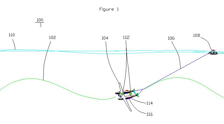
Figure 1 describes an embodiment of the present invention which is an innovative new sea gliding apparatus (100) comprising a sea glider (104), a surface sled (108), and a counterweight and anchor system (116). The sea glider (104) is connected to a surface sled (108) by a line (106) that is a hollow tube that contains a bundle of individual communication lines, air supply lines, return air lines, etc. (these lines are not individually shown in this drawing but are shown in detail in Section “AA” of Figure 2) that support the operation of the sea glider (104). The anchor system (116) provides the ability to anchor the sea glider into a stationery position underwater or may be readily detached so that the sea glider (104) may float high above the water’s surface (110) like a conventional surface vessel. Further, all three components, the sea glider (104), the surface sled (108), and the anchor system (116) may be coupled to together to from a single vessel (not shown).
The sea glider (104) follows a wave pattern glide path (102) through the water below the surface (110) of the water. On-board power for the sea glider (104) is derived by harnessing the kinetic energy of motion through water via hydro-turbines (112) mounted on the sea glider (104).
The surface sled (108) travels on the surface of the water (110) and provides additional power via a wind turbine and via solar power (these are not individually labeled on this drawing but are shown in detail in Figure 2).
Thrusters (114) mounted on the sea glider (104) provide thrust for the sea glider via power provided by the surface sled (108) or using stored electrical power, etc.
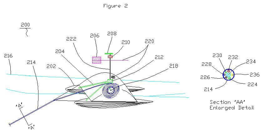
Figure 2 is a detail of the surface sled apparatus (100) cited in Figure
1. The surface sled (100) floats on the surface of the water (216) having
pontoons (202) for floatation and it is pulled through the water by the
sea glider (not shown) of Figure 1.
A wind turbine (206) is coupled to the surface sled (200) to harness a portion of the kinetic energy of motion of the wind turbine’s (206) movement through the air. An air compressor (212) is coupled to the shaft (222) of the wind turbine (206) and a supply of compressed air is produced by the air compressor (212) and the compressed air is stored in the pontoons (202). Compressed air is supplied to the sea glider (not shown) by a line (214) that is connected to the sea glider as shown in Figure 1.
The line (214) is a hollow tube that contains a bundle of individual lines: fiber optic cable (224), electrical supply line (226), radar communication line (228), GPS communication line (230), high pressure air supply line (232), low pressure return air line (234). The length of the line (214) between the surface sled (200) and the sea glider of Figure 1 (not shown) is controlled by a line reel (218) onto which the line (214) is wound. Compressed air lines (204) supply compressed air from the compressor (212) to the pontoons (202) and to the line (214) via the line reel (218) to supply air to the sea glider of Figure 1. Stored compressed air is supplied to the line (214) from the pontoons (202) via the line reel (218) to supply air the sea glider of Figure 1 as well.
Additional power is generated on the surface sled (200) by solar cells (220) that are mounted on the upper surfaces of the surface sled (200) and are mounted on the upper surfaces of the disk shaped wind turbine (206).
A telescopic camera (208) that has a fiber optic cable (not shown) connected to the sea glider (not shown) of Figure 1 by the line (214) is mounted on the surface sled (200) for visual communication of the surface of the water (216) by occupants of the sea glider of Figure 1. A radar unit (210) that has a communication line (not shown) connected to the sea glider of Figure 1 by the line (214) is mounted on the surface sled (200) so that occupants of the sea glider of Figure 1 are provided radar (210) surveillance of the surface of the water (216).
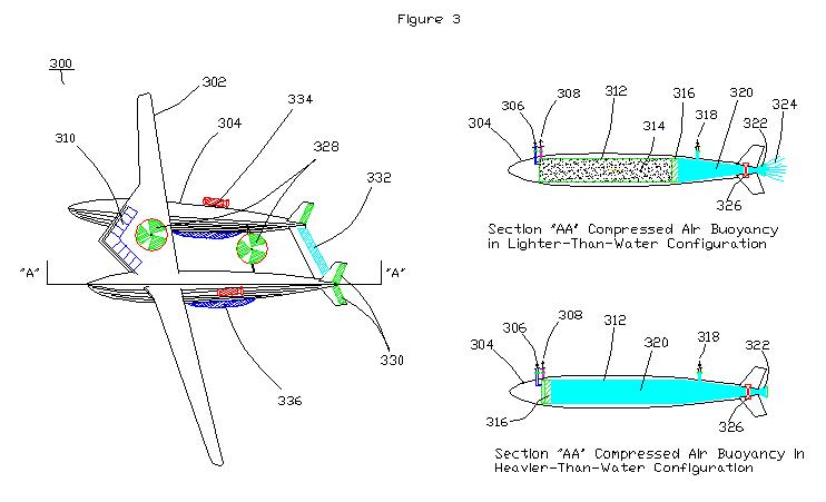
Figure 3 provides a detail of the lifting body pontoons (304) of the sea glider (300) that has long narrow, high aspect ratio wings (302) connected to the pontoons (304). Ailerons (332) and rudders (330) provide control for the sea glider (300) to glide through the water. A cabin area (310) for the crew and passengers is located in a Delta wing section of the sea glider (300) positioned between the two lifting body pontoons (304). Hydro-turbines (328) are coupled to the sea glider (300) to produce power from the motion of the sea glider (300) through the water or the tidal flow of water over the sea glider (300) when it is stationery. The sea glider (300) is held in the stationery position by an anchor counterweight system (336) mounted underneath the lifting pontoons (304). Cargo (not shown) is stored underneath the cabin area (310).
Thrusters (334) provide thrust for propulsion of the sea glider (300) and the surface sled (not shown) coupled to the sea glider (300). Power is produced by the hydro-turbines (328) and a portion of the power may be used for guidance control via the thrusters (334). Power may be stored in storage batteries (not shown) or may be supplied by the surface sled (not shown) via wind its wind turbines (not shown) or via compressed air stored on the surface sled within its pontoons (not shown).
The lifting body pontoons (304) provide ballast for the sea glider (300) and can be changed from the heavier-than-water mode of operation to the lighter-than-water mode using compressed air (314) that is supplied by the surface sled of Figure 2 that is not shown. The compressed air (314) flows through control valve and line (306) into a cylinder (312) on one side of a piston (316), causing the piston (316) to move backward in response to the pressure applied by the compressed air (314) displacing water (320) from the pontoon (304) through control valve (326) in order to make the lifting body pontoon (304) lighter-than-water in order to provide an upward motive force via the principal of buoyancy. Thrust (324) is provided by this process via Newton’s Third Law as the pressurized water (320) flows through jet propulsion nozzle (322). The thrust (324) provides propulsion for the sea glider (300).
The propulsion produced by the thrust (324) of the jet propulsion nozzle (322) maintains the velocity of the sea glider (300) as it changes ballast. Otherwise, the sea glider (300) would lose velocity at it makes the transition from being heavier-than-water to being lighter-than-water and neutral buoyancy is attained that does not provide buoyancy acceleration via positive buoyancy, creating an upward motive force, nor does it provide gravity acceleration via negative buoyancy to create a downward motive force for the sea glider (300) to sea glide.
In order to change ballast to the heavier-than-water mode, the compressed air (314) is released from the pontoon (304) through control valve and line (308). The piston (316) moves forward in response to hydro-static pressure applied against the piston (316) by the water (320) on the backside of the piston (316) and water that flows through control valve (326) to fill the pontoon (304) in order to make it heavier-than-water.
Alternately, in order to change ballast to the heavier-than-water mode, the compressed air (314) is not released from the pontoon (304), but is compressed within the pontoon (304) to a much smaller volume and to a much higher pressure. Control valve (326) is closed and high pressure water (320), having a much higher pressure than the hydro-static pressure of the surrounding water (320), is supplied by a hydraulic pump (not shown) connected to the shaft (not shown) coupled to the hydro-turbines (328) on the sea glider (300) to the cylinder (312) within the pontoon (304) through line and control valve (318) on the side of the piston (316) opposite the compressed air (314) side of the piston (316). The piston (316) moves forward in response to pressure applied against the piston (316) by the incoming high pressure water (320) in order to make the lifting body pontoon (304) heavier-than-water as the compressed air (314) undergoes a higher level of compression and its physical volume undergoes a dramatic reduction in cubic area.
The advantage gained by this alternate method of operation is that greater depth may be gained by the sea glider (300). The very high pressure compressed air (314) is used later to provide lift at greater depth by opening control valve (326) allowing the compressed air (314), having far greater pressure than the hydro-static pressure of the surrounding water (320), to expand to a greater volume, which causes the piston (316) to move backward in response to the extreme high pressure compressed air (314). The piston (316) displaces water from the lifting body pontoon (304) through control valve 326) and thrust (324) is provided as the pontoon (304) becomes lighter-than-water to provide buoyancy for the sea glider (300).
Propulsion may also be provided by compressed air (314) stored in the pontoons of the surface sled (not shown) of Figure 2. The compressed air (314) powers pneumatic motors (not shown) that power the thrusters (328).
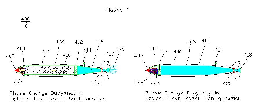
Figure 4 describes an alternative embodiment that uses
phase change as a method of operation of the sea glider (not shown) to
provide buoyancy. A high vapor pressure low-boiling-point-liquid (426)
is vaporized by a resistance heating element coil (404) and by RF frequency
microwave heating (402) to create buoyancy in lifting body pontoon (406).
As the liquid (426) becomes high pressure vapor (410), the high pressure
vapor (426) forces piston (412) backward within cylinder (408), which
in turn forces a jet propulsion (420) flow of pressurized water (416)
through control valve (422) and through jet propulsion nozzle (418) out
of the pontoon (406) to cause the sea glider (not shown) to become lighter-than-water
as jet propulsion thrust (420) is obtained to provide propulsion for the
sea glider.
A liquid low-boiling-point-liquid (426) pump (424) pressurizes liquid
(426) through the resistance heating element coil (404).
The sea glider (not shown) becomes heavier-than-water as the vapor (410) is circulated through heat exchange coils (not shown) that reject heat to the water (416) that surrounds the pontoons (406), which causes the vapor (410) to phase change to the liquid (426) state as the temperature drops. A phase change is facilitated by a drop in temperature and an increase in pressure. The pressure of the vapor (410) may be increased by pumping high pressure water (416) into the area on the opposite side of the piston (412) within cylinder (408) through control valve and high pressure water supply line (414). The increase in pressure helps to cause the vapor (410) to change phase to the liquid (426) state as the vapor (410) is rejecting heat to the environment.
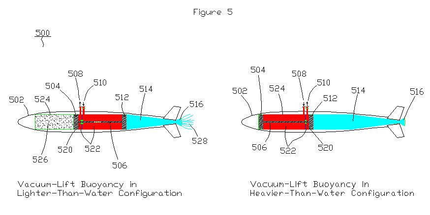
Figure 5 describes an alternative embodiment that forms a vacuum (526) as a method of operation of the sea glider (not shown) to provide a buoyancy-lift apparatus (500). Buoyancy to make the sea glider lighter-than-water is created as a vacuum (526) is formed as piston (512) is forced backward within cylinder (524) by pressurized hydraulic fluid (522) that flows into the cylinder through control valve and supply line (510) applying a force against piston (512). Piston (512) is coupled to piston (504) by a rod (506) so that piston (512) and piston (504) move in concert. As piston (504) moves backward in concert with piston (512), a vacuum (526) is formed within cylinder (524) forward of piston (504); and, water (514) is forced through jet propulsion nozzle (516) and out of pontoon (502) to create thrust (528) for propulsion of the sea glider (not shown).
Hydraulic fluid (522) is withdrawn via a hydraulic pump (not shown) through line (508) from the left side of a wall and rod seal (520), which prevents the flow of hydraulic fluid (522) from flowing from one side of the wall and rod seal (520) to the other side of the wall and seal (520) along the rod (506), and is pressurized into the right side of the wall and rod seal (520) that causes piston (512) to move backward as described above to form the vacuum (526).
The heavier-than-water mode of operation is established by releasing the vacuum (526) and allowing the piston (504) to move forward and piston (512) moves forward in concert with piston (504) and hydraulic fluid (522) flows from the right side of wall and seal (520) through control valve and line (510) to the left side of wall and seal (520) through line (508) until no vacuum (526) remains and the vacuum-lift is lost.