The Matrix is a boat builder's or aircraft manufacturer's dream come true -- a lightweight composite material that you simply apply resin to and lay into a mold ! The Matrix process automatically produces a lightweight, unsinkable triple hulled boat or an airplane with a triple skin that has continuous internal ribs and spars that provide superior strength at the same time the Matrix provides excellent floatation and a high degree of insulation, using sealed cell foam imbedded within high-strength structural composite material walls. Flexi-Beam and Rigid Beam are formed by manufacturing a fiber sleeve that may be fiberglass, carbon fiber, or Kevlar, etc. over a flexible core material (sealed cell foam) or a rigid core material. Individual pieces of Flexi-Beam or Rigid Beam material are laid in place and bonded together to form the Matrix dual-axis, dual-plane geometry. Flexi-Beam conforms to any shape; and, as the name implies, Rigid-Beam makes a flat surface that is usable for bulkheads and decks or any other purpose for which a high strength, lightweight panel may be required. |
|||
Pricing
for a Flexi-Beam or for a Rigid-Beam
sample kit to make a Matrix geometry test panel that
is 2' X 2' of fiberglass |
|||
| Pricing
for a Flexi-Beam or for a Rigid-Beam
sample kit to make a Matrix geometry test panel that
is 2' X 2' of carbon fiber composite material is one hundred ninety-five dollars ($195.00) plus freight and handling. |
|||
The Matrix geometry process begins with a layer of fiber that is placed in the bottom of a mold. This layer forms the lower outer layer of the Matrix structure that is being constructed. In boat building a layer of gel-coat would be sprayed into the mold before the fiber is applied. |
 |
||
| Flexi-Beam sections that run in the Y-Axis direction conform to the shape of the mold are laid in place to form the equivalent of ribs on a boat or airplane | 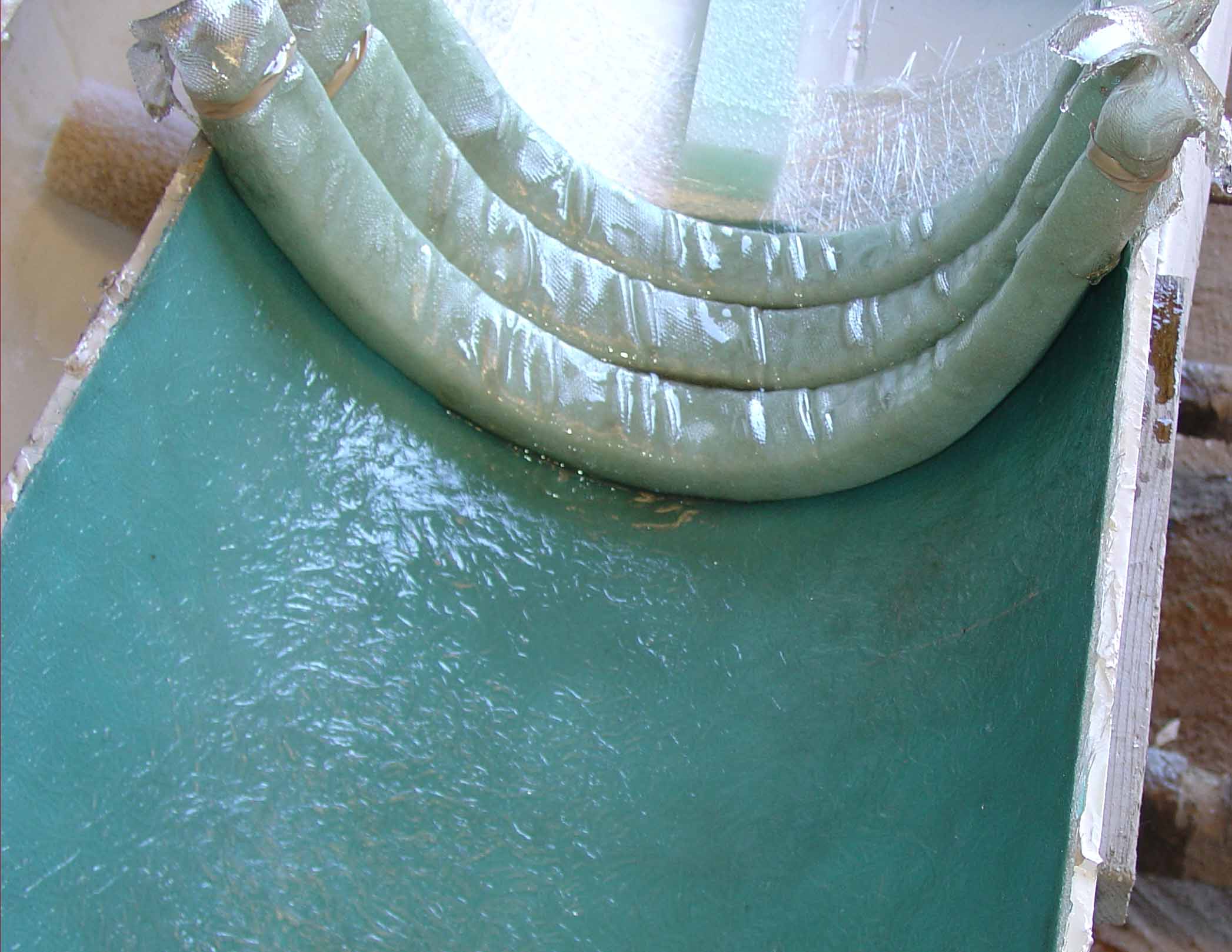 |
||
| In this photo you can see that the Y-Axis ribs form a continuous layer or plane. This is the first plane of the dual-plane, dual axis Matrix geometry. Notice that the Flexi-Beam sections touch and therefore will bond together as a single layer | 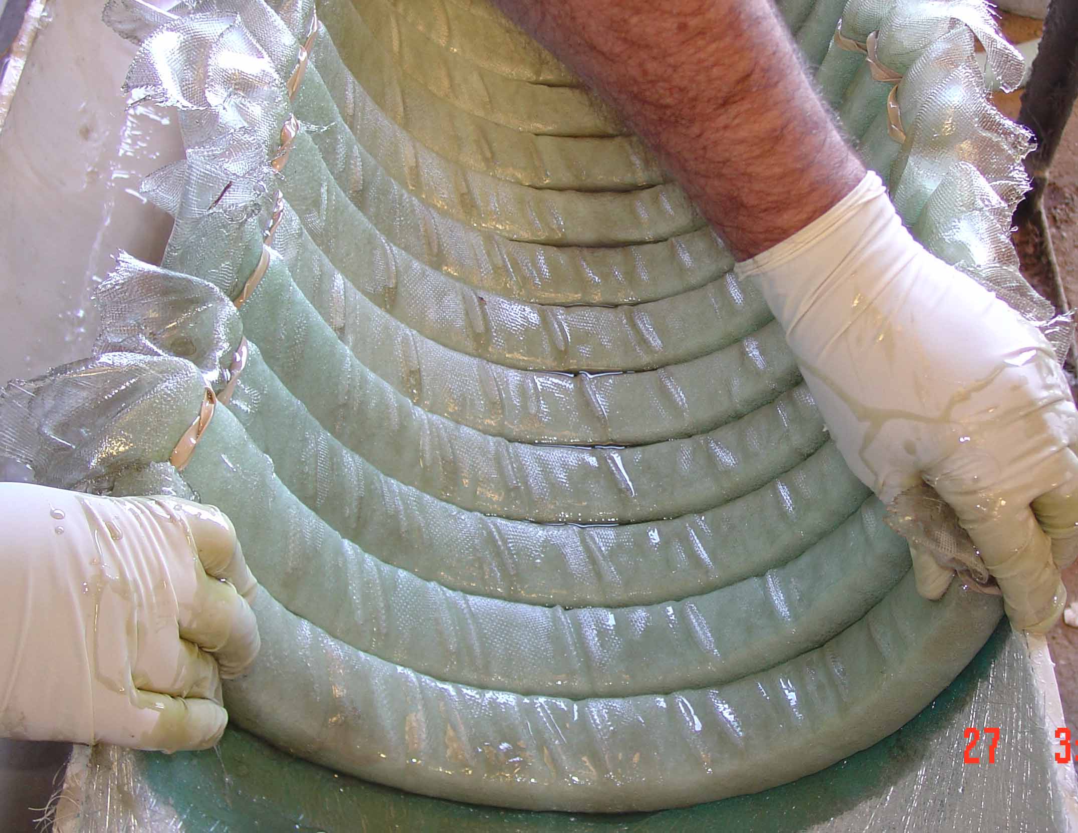 |
||
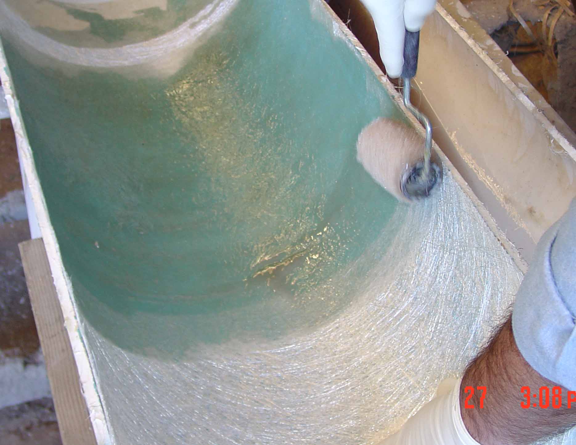
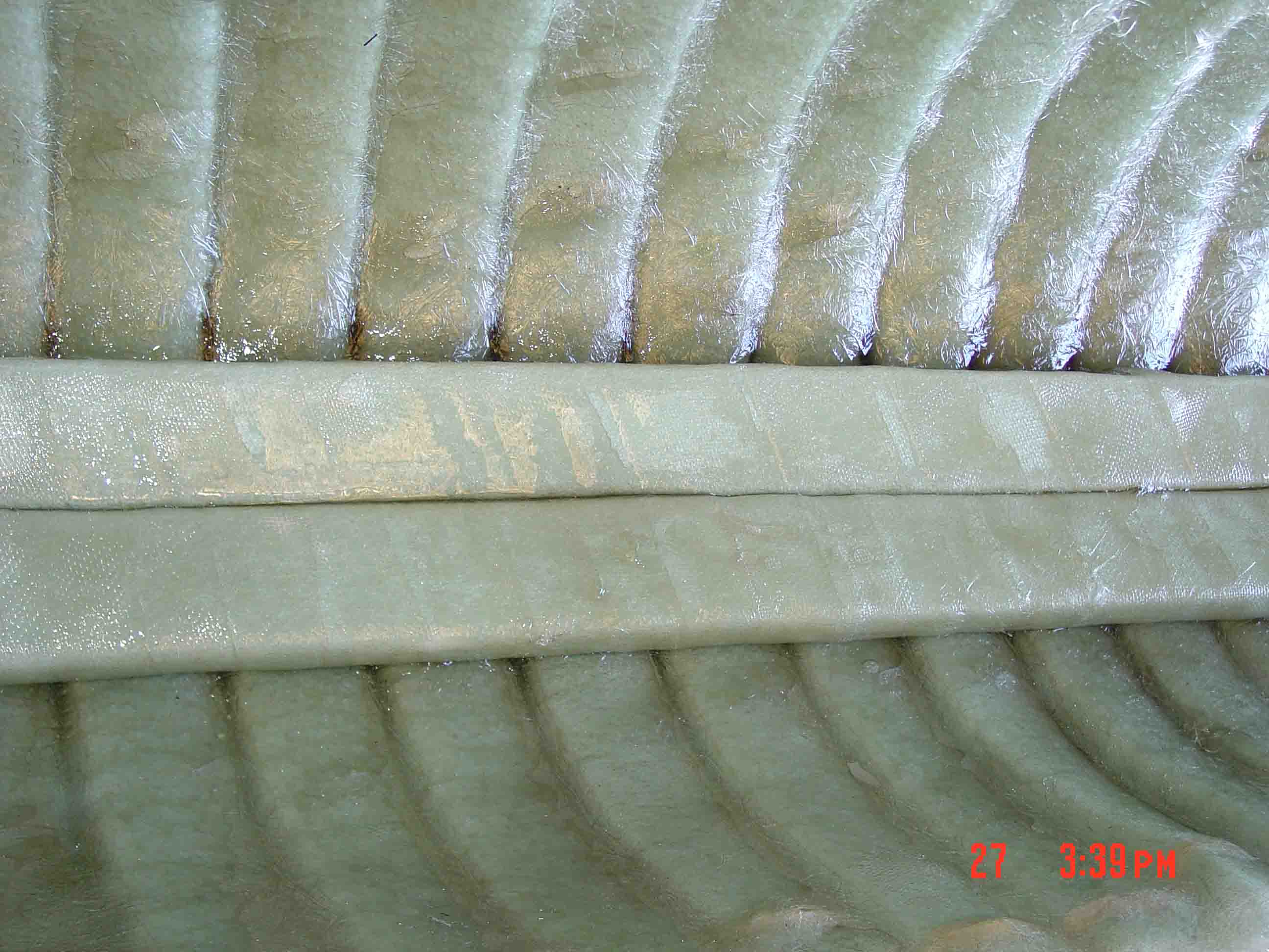
| Over the Y-Axis lower plane, a center bonding layer, which is a flat sheet of composite fabric, is laid over the ribs. Resin is applied to this center bonding layer and the center bonding layer forms a center wall within the Matrix geometry that serves the important purpose of bonding all of the individual sections of Flexi-Beam together. As the next step takes place, this bonding layer will also bond together all of the X-Axis Flexi-beam sections that are laid over this center bonding layer as you will see. | 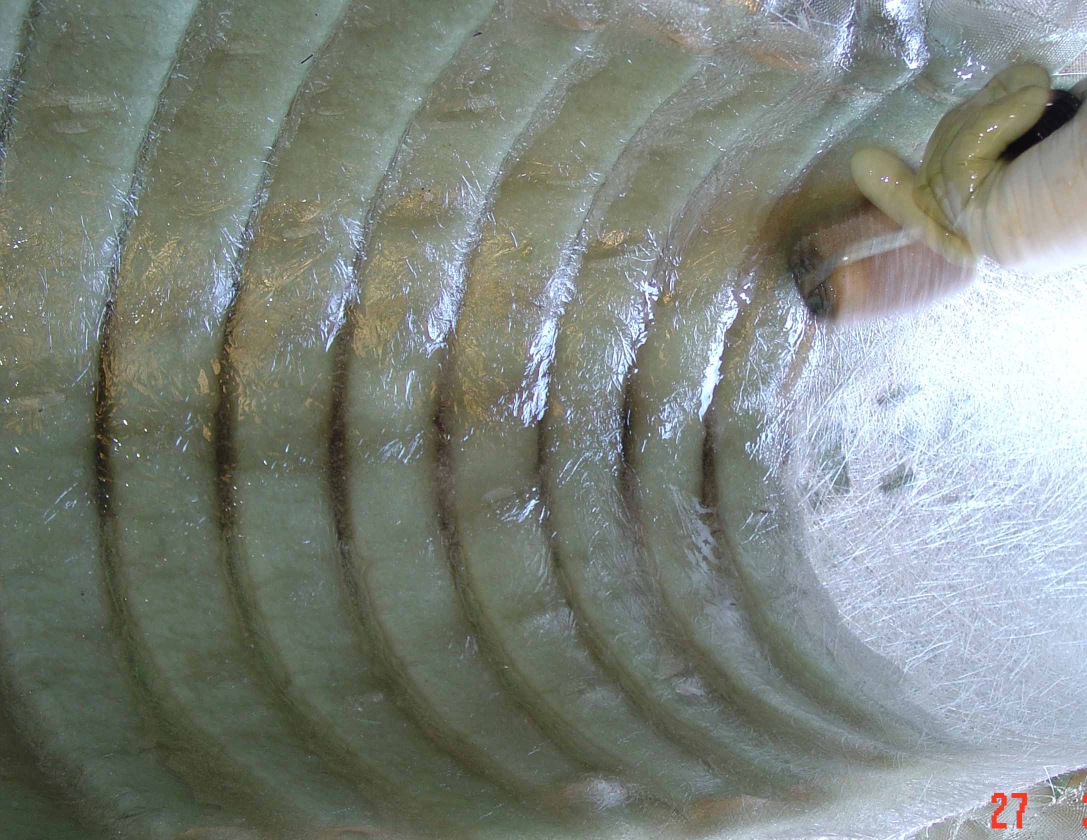 |
||
Now, you can clearly see the dual-plane, dual axis Matrix geometry as the first Flexi-Beam sections are laid in the X-Axis direction over the center bonding layer. The X-Axis provides the equivalent of spars. Here you can easily see the ribs and spars that are bonded together to create the Matrix geometry and understand why it produces such superior strength. Essentially, continuous ribs and spars that are bonded together are created by the Matrix geometry. |
 |
||
| A layer of fiber material is applied over the X-Axis layer of Flexi-Beam to form the top surface of the Matrix dual-axis, dual plane composite material structure. | 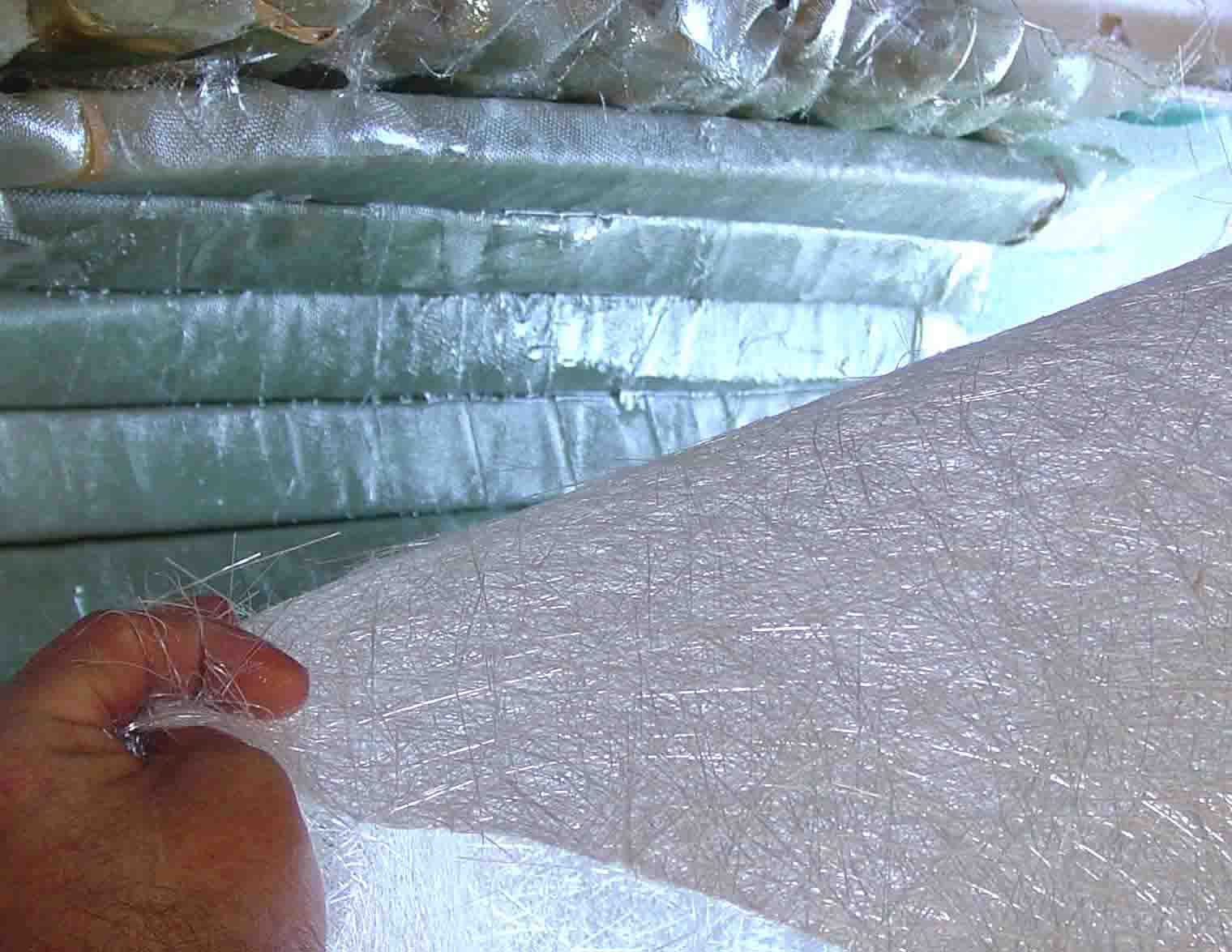 |
||
| The top outer layer has resin applied and the wet lay-up is cured to form the finished Matrix. | 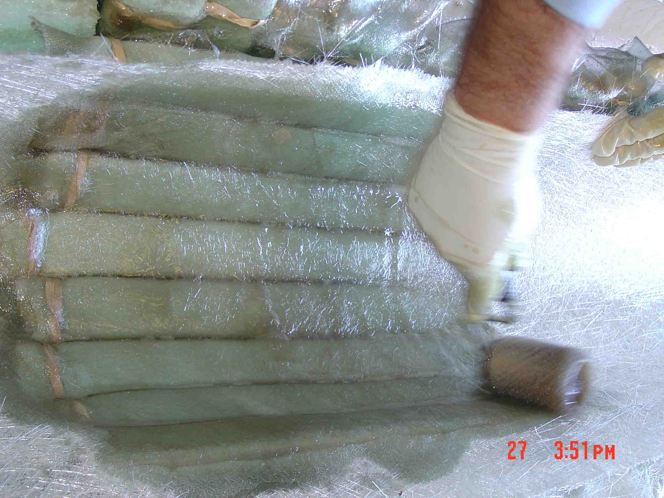 |
||
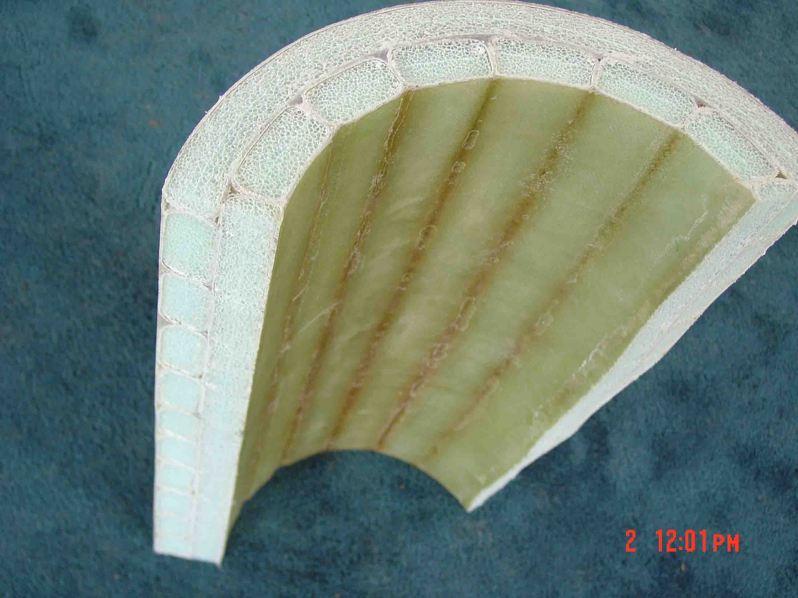
Here is the finished product after the edges have been cut off. In this photo the unique Matrix geometry is easy to recognize. |
 |
||
An incredibly strong three hull boat with internal floatation and insulation is created by use of the Matrix as shown is this detail. The Matrix geometry produces so much strength that conventional ribs and stringers are not needed. Within the fiber walls of the Matrix is sealed cell foam core that provides Coast Guard approved floatation and excellent insulation capability. |
 |
||
| In this photograph the tremendous degree of floatation of the Matrix is quite evident. It floats so high on top of the water that it looks like it is merely placed on a black table top. | 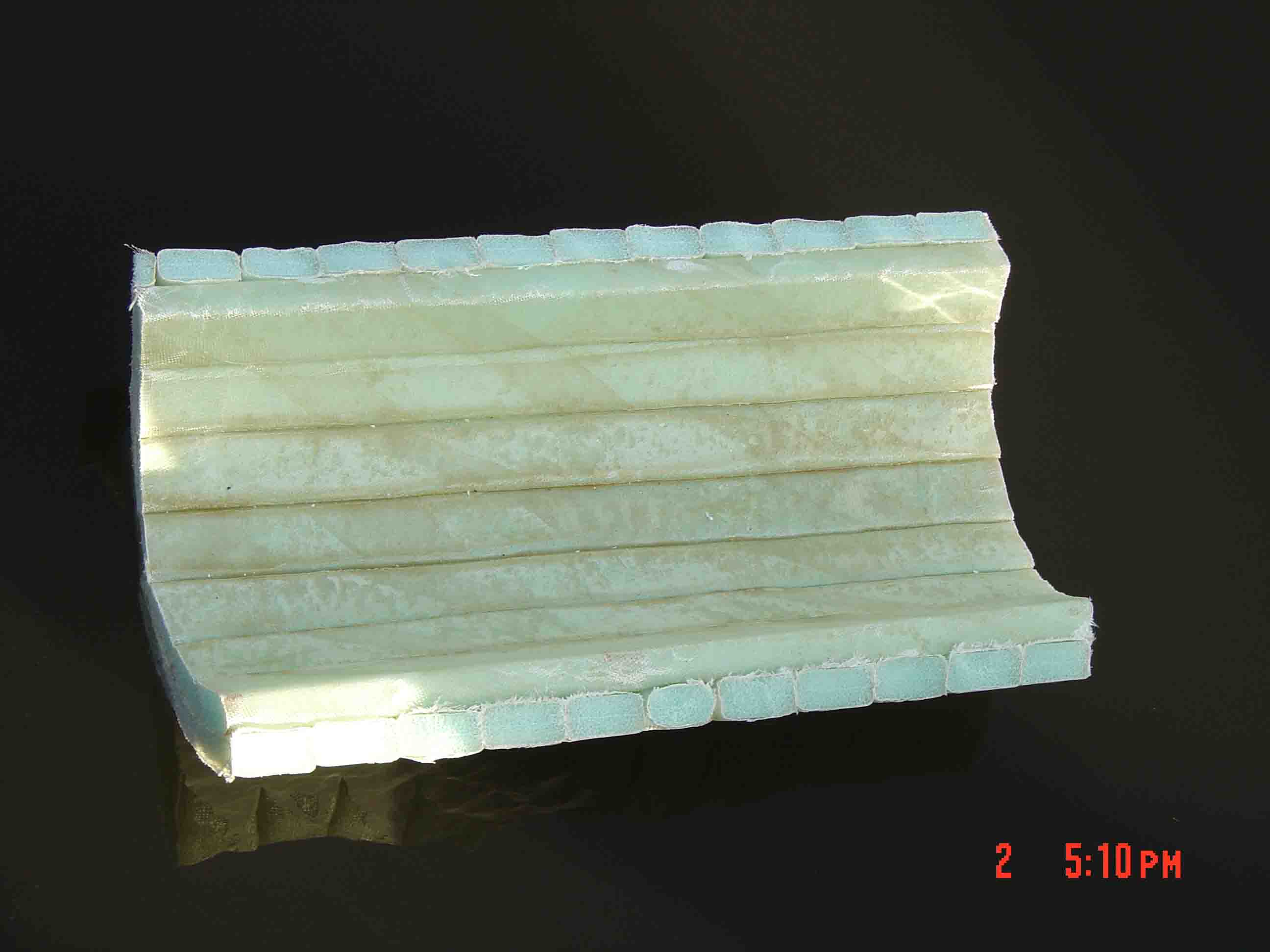 |
||
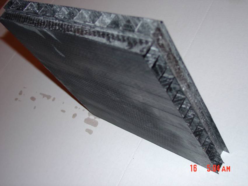
This Matrix flat panel is made with lightweight carbon fiber with no core material, which produces and extremely low density high, strength material. It is manufactured using the pultrusion process. Initial Tests of this Matrix product is being conducted by the Polymer Department at the University of Southern Mississippi. Our early results indicate that it is perhaps the highest strength-to-weight ratio composite material geometry that is known to exist. |
 |
||
| This product is not in production yet, but we hope to have it commercially produced within the coming months as we are currently holding discussions with potential joint venture partners for the manufacture of this dual-plane, dual-axis Matrix geometry product. | 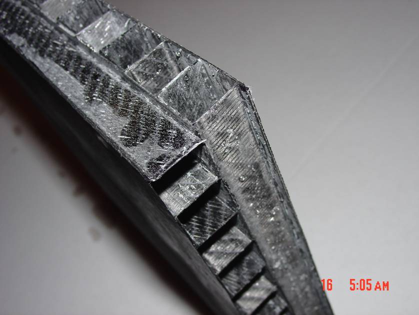 |
||
The Underlying Science of the Patent Pending Dual-Plane, Dual Axis High Strength Matrix Material By: Robert D. Hunt, Inventor When I began to the search for materials from which to build the gravityplane, I studied the conventional state-of-the-art materials used in the manufacture of aircraft. What I discovered was that the existing composite materials technology is not strong enough, is not light enough, and that is has a severe delamination problem due to its construction technique. I soon realized that I could never build the gravityplane with the existing composite materials technology. The Problems with Conventional Composite Materials Technology The common method of forming composite material sections is to sandwich a core material, usually honeycomb core or foam core materials, between two outer layers of fiber that are bonded with an epoxy resin. The core material provides stiffness. The weakness of this geometry is that the core material does not contain fiber. It is fiber that provides real strength. Secondly, the weaker core material often poorly bonds to the fiber outer layers. When a section of conventional composite material undergoes extreme stress, the core material separates (delaminates) from the outer fiber layers and overall weakness occurs that can cause severe problems, like the catastrophic failure of the Airbus tail sections. To summarize the existing materials technology, there is minimal strength at the center of conventional composite material construction. The only real strength is the fiber at the outer surfaces; and, these two surfaces are poorly connected together by core material and the core provides too much weight. To make matters worse, the core material is rigid and does not conform to irregular or curved shapes without cutting the rigid core materiel into small pieces that only partially bond to the outer fiber material at the edges of the core material where glue is applied and voids are formed. This is a common practice in boat building where rigid core is placed in the bottom of a curved boat hull. The Theory of the Matrix At this point I knew I had to find a better way, so I approached the problem in a logical manner. When you think of building a strong conventional structure, such as a house, you immediately think that you need a frame to support the top and sides of the structure. Your frame normally would consist of at least two vertical members running in the X-Axis if viewed from above, with trusses running in the Y-Axis direction over the top of the vertical members so that the vertical members support the trusses. The vertical support members and the trusses become weaker if they occupy the same plane, because at the intersection where they meet a weak junction is formed, instead of the stronger geometry of the trusses resting on top of the vertical support members. This configuration forms a dual-axis (when viewed from above), dual-plane geometry that provides superior structural strength that I named the Matrix. The Matrix geometry can, likewise, be applied to a single flat panel or a curving panel to provide superior strength. Additionally it is well known that a sealed sectional modulus, as is commonly used to form a square or a rectangular metal or composite tubing, provides strength. Note that the above composite panel is comprised of a parallel series of sealed sectional modulus running in the X-Axis direction and a parallel series of sealed sectional modulus running in the Y-Axis direction to form the panel. The panel is a single bond to form a complex composite structure having high strength and low weight that provides an excellent weight-to-strength ratio. Additional strength and stability, especially as relates to side-loading, may be produced by the use of angled braces between the vertical members and we have developed a number of different geometry with angled support members. However, the walls of the standard Matrix design are generally so short in relationship to a large surface area panel and so stiff that they shatter before deflecting to the side when made of carbon fiber; therefore, angled support members have had little value in most of the uses for the Matrix thus far. An extremely important innovation in the design of the Matrix is the center bonding layer. This layer eliminates the potential of delamination as it securely bonds the upper plane to the lower plane of the Matrix's dual planes. We have constructed prototype panels leaving the bonding layer out to see the difference and the strength of the panel is far less than the strength and stiffness of the normal panel with the bonding layer included. The Matrix solves the issues related to conventional boat or aircraft construction materials: it is far lighter in weight because the core material is eliminated, the strength and stiffness begins with the center bonding layer that securely bonds the upper and lower planes together so that it cannot delaminate, and it can be readily formed to any shape. The Innovation of Flexi-Beam When we began our Matrix product prototype development work, we discovered that it was extremely difficult to get the resin into interior walls because the core sections applied pressure against both sides of the vertical fiber walls that blocked the flow of resin down into the interior vertical wall sections. To solve this problem I created the Flexi-Beam or Rigid-Beam, which is a length of core material that may be either flexible or rigid over which a fiber sleeve is placed. Resin is applied to each beam individually and then when two beams are placed side by side, resin in already on both of the vertical adjacent walls and the strength of the wall is double because two separate walls meet and bond together to make one stronger wall. The Flexi-Beam or Rigid-Beam are building blocks to construct the Matrix. However, we soon realized that the Flexi-Beam and Rigid-Beam were extremely useful as stand alone building materials. If you want to make a beam in a circular shape, bend Flexi-Beam into a circle and apply resin. A Flexi-Beam can be used to form almost any desired shape. Only your imagination limits what you can make with Flexi-Beam. All you have to do is bend the Flexi-Beam to the desired shape and apply a resin to cure the beam into a lightweight, strong, rigid structure. And, any two Flexi-Beams or Rigid Beams may be connected, merely by placing them together and applying resin to make a firm bond. This eliminates the need for other forms of fasteners, such as screws, nails, etc. to build a structure. Uses of the Matrix: |
|||
New Triple Hull Boat Construction Boat Repair Aircraft Construction and Repair Support Beams Vertical Axis Wind Turbine Disks and Shutters Wind Turbine Powered Pontoon Boat Floating docks Piers |
Roofing Material Flooring Material Forms for Construction Scaffolding Boards Portable Buildings Bridge Construction Reinforcement Material |
||